-
Descriptions

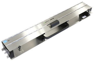
The CCI is used to couple EFT/burst pulses to I/O lines as required in different European and international standards for immunity testing.
The coupling of the Electrical Fast Transients EFT/burst to signal lines can usually not be achieved by discrete capacitive coupling without interfering with the signal flow. It is often impossible to contact the required circuit (direct), e. g. coaxial or shielded cables. In this case the coupling is realized by the capacitive coupling clamp. The interference simulator can be connected on both sides of the coupling clamp.
The IEC 61000-4-4 Ed 3.0 published 2012 recommends the calibration of the capacitive coupling clamp into a 50ohm coaxial load with the normative calibration kit CCI PVKIT 1. -
Highlights

- As per IEC 61000-4-4 Ed.3
- EFT/BURST testing of signal and datalines
- Active coupling length 1m
- Permissable burst voltage 7 kV
- Cable diameter up to 40 mm
- Calibration kit for capacitive coupling clamp as per IEC 61000-4-4 Ed.3
- Extension for the PVF BKIT 1 for capacitive coupling clamp calibration with EFT/burst
- Support provided to adapt the load resistors on 100 mm height level
- Flexible transducer plate 1,050 x 120 mm (optional) -
Benefits

CCI PVKIT 1 calibration set-up
Calibration of the capacitive coupling clamp
The standard IEC 61000-4-4 Ed 3.0 recommends a new calibration of the capacitive coupling clamp. EMTEST developed for the calibration, the CCI PVKIT 1 set.
Components required for carry out the calibration:
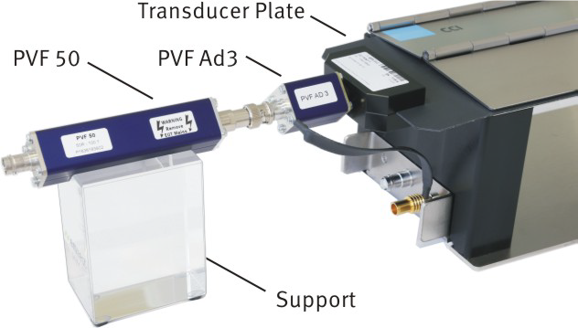
CCI PVKIT 1: Consisting of transducer-plate and support
PVF 50: Load resistor 50ohm
PVF AD 3: Adapter 4 mm for connect the transducer-plate to the coaxial SHF connector of PVF 50
Calibration set-up
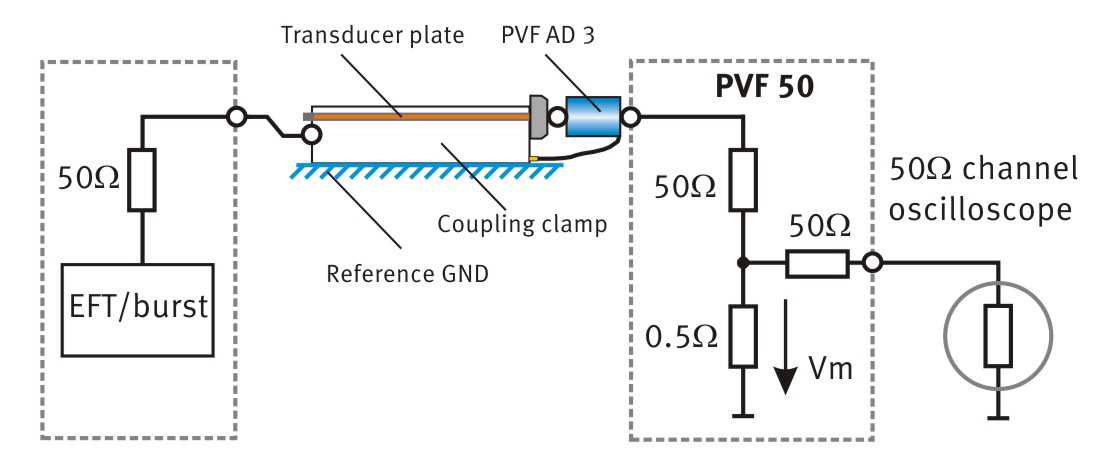
The transducer plate shall be placed into the capacitive coupling clamp such that the end with the connection is aligned with the end of the coupling plate. The connecting adapter PVF AD 3 is bond with a low impedance connection band to ground reference plane for grounding of the 50ohm coaxial measurement terminator/attenuator. The load resistor PVF 50 is connected to the PVF AD 3 adapter. An acrylic support places the PVF 50 to the same 100 mm height as the coupling clamp is distant from the reference ground.
The distance between the transducer plate and the PVF 50 measurement terminator/attenuator shall not exceed 0,1m. A setup example is given in figures on this datasheet.

Coupling Clamp calibration
The calibration of the capacitive coupling plane is performed with the open circuit voltage setting at the EFT/burst generator (50 ohm output): 2,000 V
Resulting output voltage across the PVF 50
(50ohm matching resistor): 1,000 V.
Measuring voltage Vm: 10 V
Measured voltage considering the 50 ohm input impedance of the oscilloscope: 5 V
Resulting attenuation (theoretical): 400:1

-
Applications
我是中標題

IEC 61000-4-4
EN 61000-4-4
IEC 61000-4-18
EN 61000-4-18


